Machine Control IMC 400
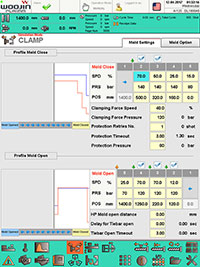
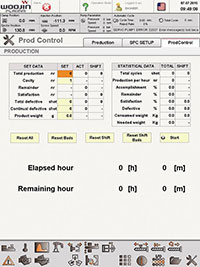
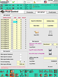
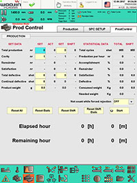
| The machine control IMC 400 is presenting all data well-structured and intuitively comprehensible on a 15‘‘ TFT touchscreen. | 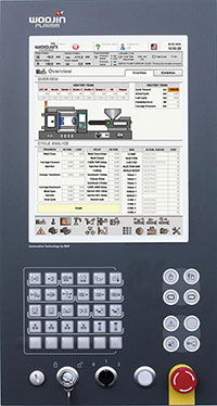 Controller IMC 400 Controller IMC 400 |
Intuitive design
The 15 inch TFT colour screen directly connected to the controller permits a very user-friendly operation by touchscreen and robust membrane buttons.
Central monitoring
- Interface integration
The software offers simple administration of the robot and other auxiliary devices. Integrated compatible interface programs such as Euromap 67 robot interface and temperature adjustment device management - Remote monitoring
The VNC server function can monitor the machine in real time anywhere and at all times. - USB interface
Many mould and parameter data can be saved via this interface. - Multi-language support
Various languages can be selected. - Error report
Simple compilation of a detailed error report
Functions
- Various setting options of the cores
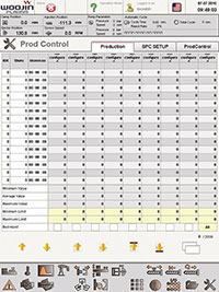
- Production data storage
- Production data analysis
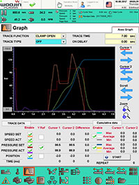
- Diagram display of the injection speed
- Robot integration
- Pre-extrusion for large injection volumes
- Heating control via automated week switching program
- Programmable lowering temperature to avoid thermal damage to the remaining material
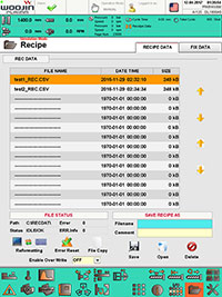
- Receipe data on internal memory with up to 1,000 files
- Sufficient memory due to a 2GB CF card
- Receipe data on external memory via USB stick
- Screenshot: Saving the screen display on the USB stick
- Injection speed, holding pressure phase “Closed-Loop” operation (optional)
- Path-time chart of the injection pressure (optional)
- Ethernet network connection possible
- Interface RS232 (optional)
- Splash-water-protected panel front (IP65)
System features
- OS: Real-time operating system
- Screen: 15 inch TFT-colour screen (1024 x 768 touchscreen)
- Simple for various accesses: Ethernet 10/100 Mbps, CAN BUS, USB, serial interface, etc.
- Guarantees for quick processing times of up to 0.4 ms: permits high control quality of time-critical applications.
Comfortable setting options
The machine control IMC400 is presented tidily: The machine functions are logically structured and presented in a good overview. Setting parameters are also presented graphically.
Alarm function
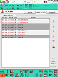
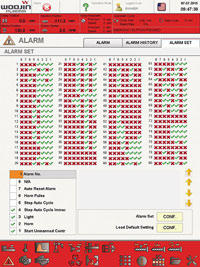
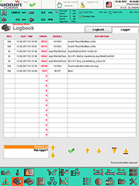
Notes and alarms are presented well-structured. Reactions can be defined for all alarms (horn, alarm lamp, ...). The log of machine alert data with time of each alert can also be printed.
Quality management
Selective data storage and management for quality assurance in up to 7 categories and 2,000 process information.
Graphical illustration
A graphic plot presents the production status and values such as injection pressure and injection speed simply and well structured.
Mould settings
More than 1000 mould-specific data records can be stored internal. The mould settings can thus be easily transferred to other controls.
Error diagnosis
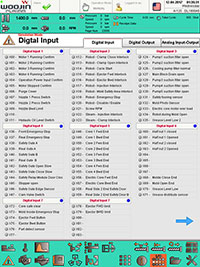
In order to simplify troubleshooting and machine diagnosis, overview pages have been created for the machine signals.
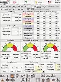
Overview of power consumption*
Precise presentation of the energy needed, referring to the entire production time. This makes it easier to assign the energy consumption per cycle. The total production time and total energy consumption amount can be displayed and used to automatically calculate energy consumption per cycle and energy used per part. Real-time energy consumption can also be displayed.
*optional
Subject to technical alterations, errors, misprint and typographical failures.


